Microchip Harmony GPIO Hello World SAMD21 Tutorial
Table of Contents
🚀 MplabX Harmony is a great framework that provides a bunch of hardware abstracted device API's which allow you to build portable applications faster. The framework supports most of the PIC32 and ARM based devices which gives you the flexibility to develop for both architectures. We are going to use the SAMD21 Curiosity nano development board in this tutorial.
Contents
- Setting Up a Harmony Project
- Launching Harmony Configurator
- Working with GPIO
- Using Harmony Libraries
Setting Up a Harmony Project 🛠️
First we need to download and install MplabX and xc32 compiler. For this tutorial we are using MplabX version v6.25 and xc32 compiler v4.60. Never versions should also work.
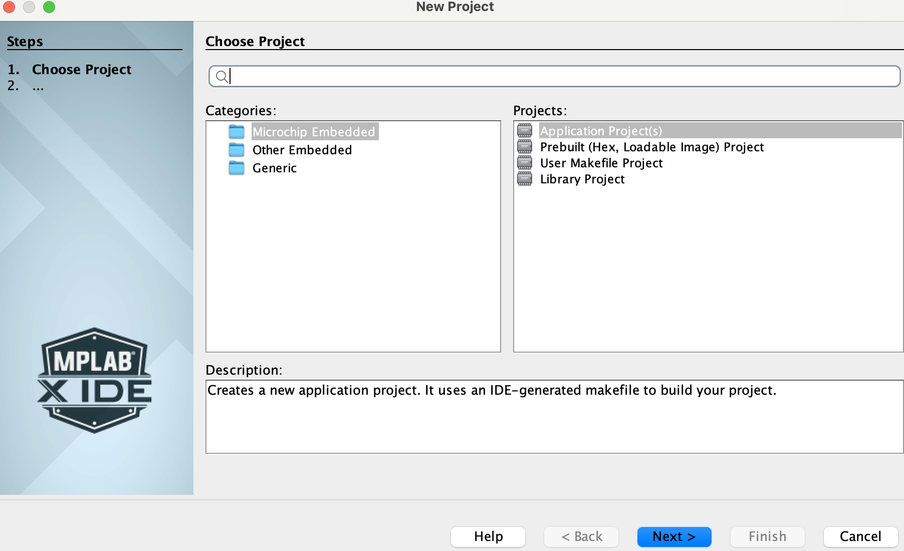
Select File -> New Project -> Application Project click next
Select the device as ATSAMD21G17D (used in this tutorial) or any other device you are using.
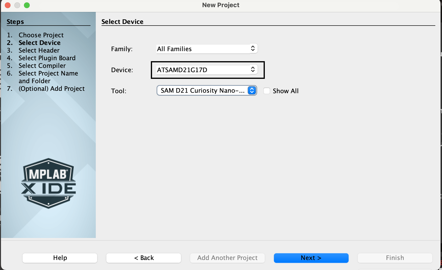
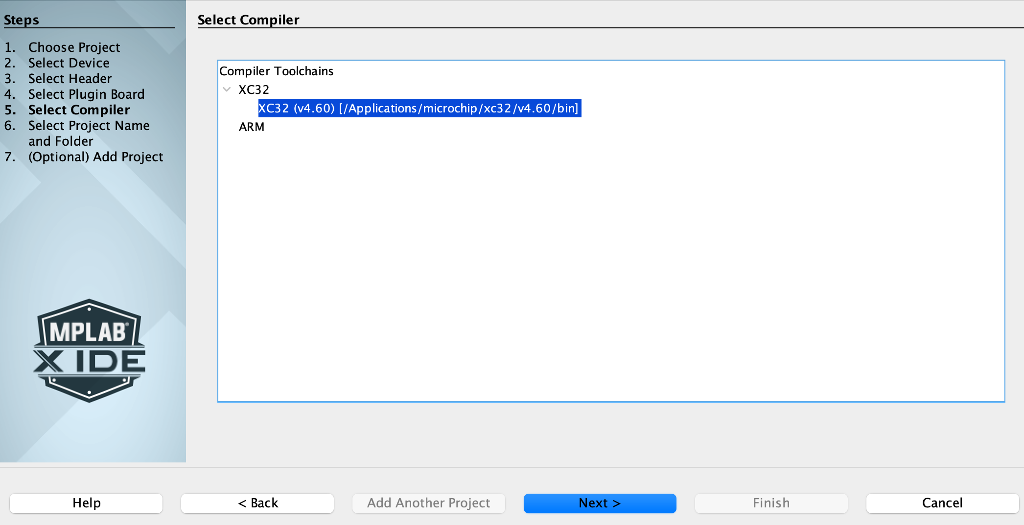
Select the compiler as XC32(v4.60) or later. Click Next >
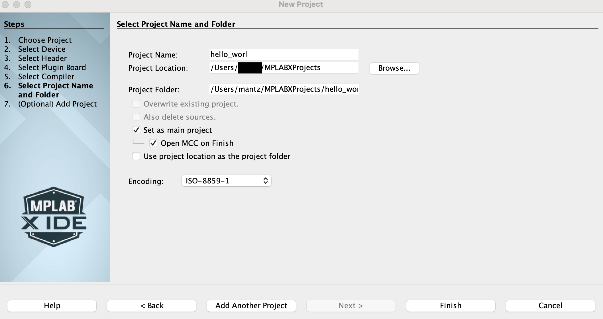
Name your project "hello_world" and keep the default project location Leave the Open MCC on Finish option selected Click Finish
Launching Harmony Configurator ⚙️
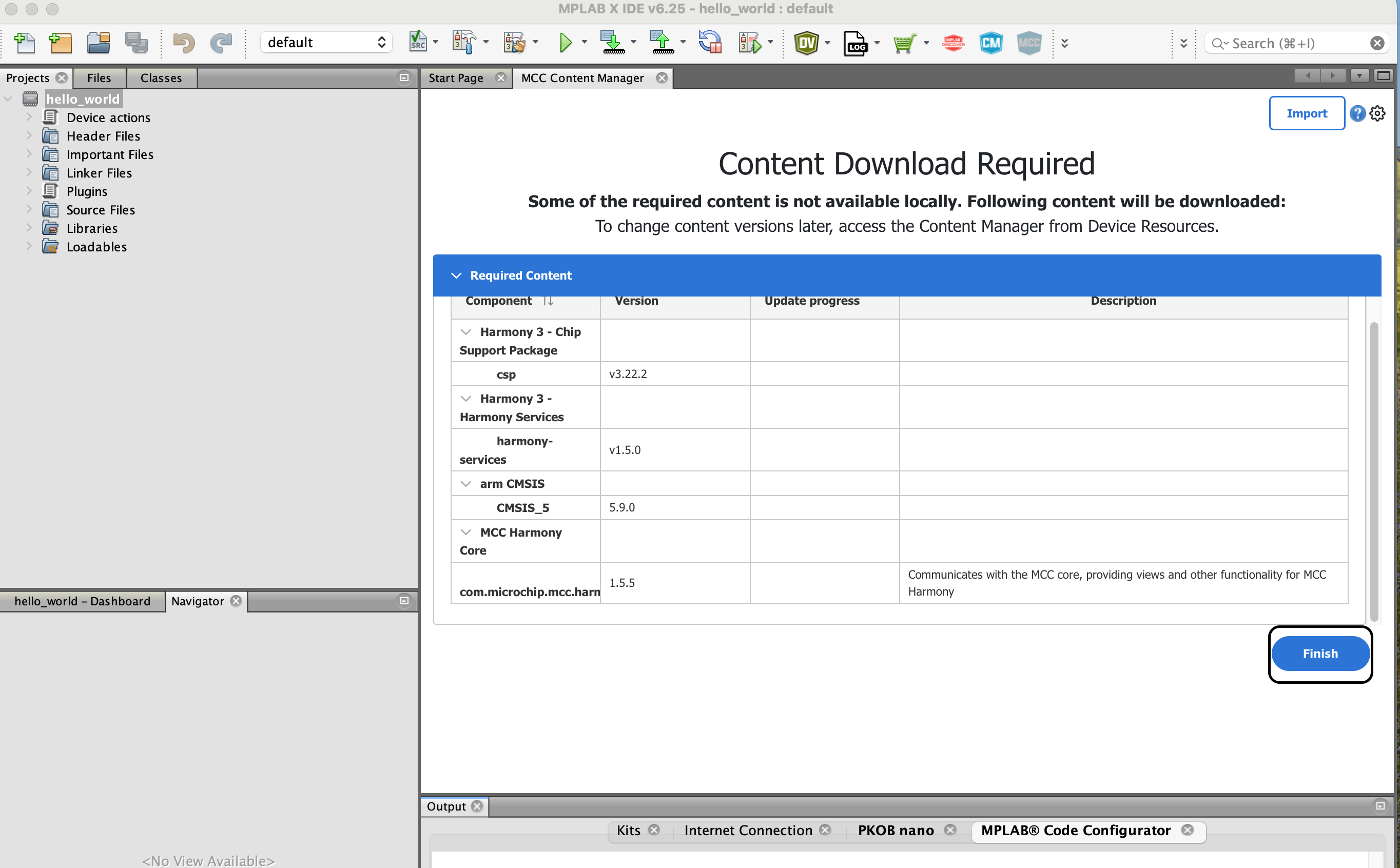
If this is your first time running Harmoy, it will need to download some of the main libraries such as Chip Support Package, Harmony 3 Services, arm CMSIS and Harmony Core. These are useful libraries that contain chip specific register files, as well as commonly used application services such as timers and console.
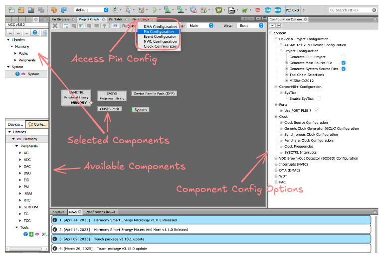
Once the download is complete you will be presented with the harmony configurator window which is split up into a number of sections, the project graph shows the currently active set of components. When any of the components are selected the corresponding sub configuration options are presented on the right under "Configuration Options" tab.
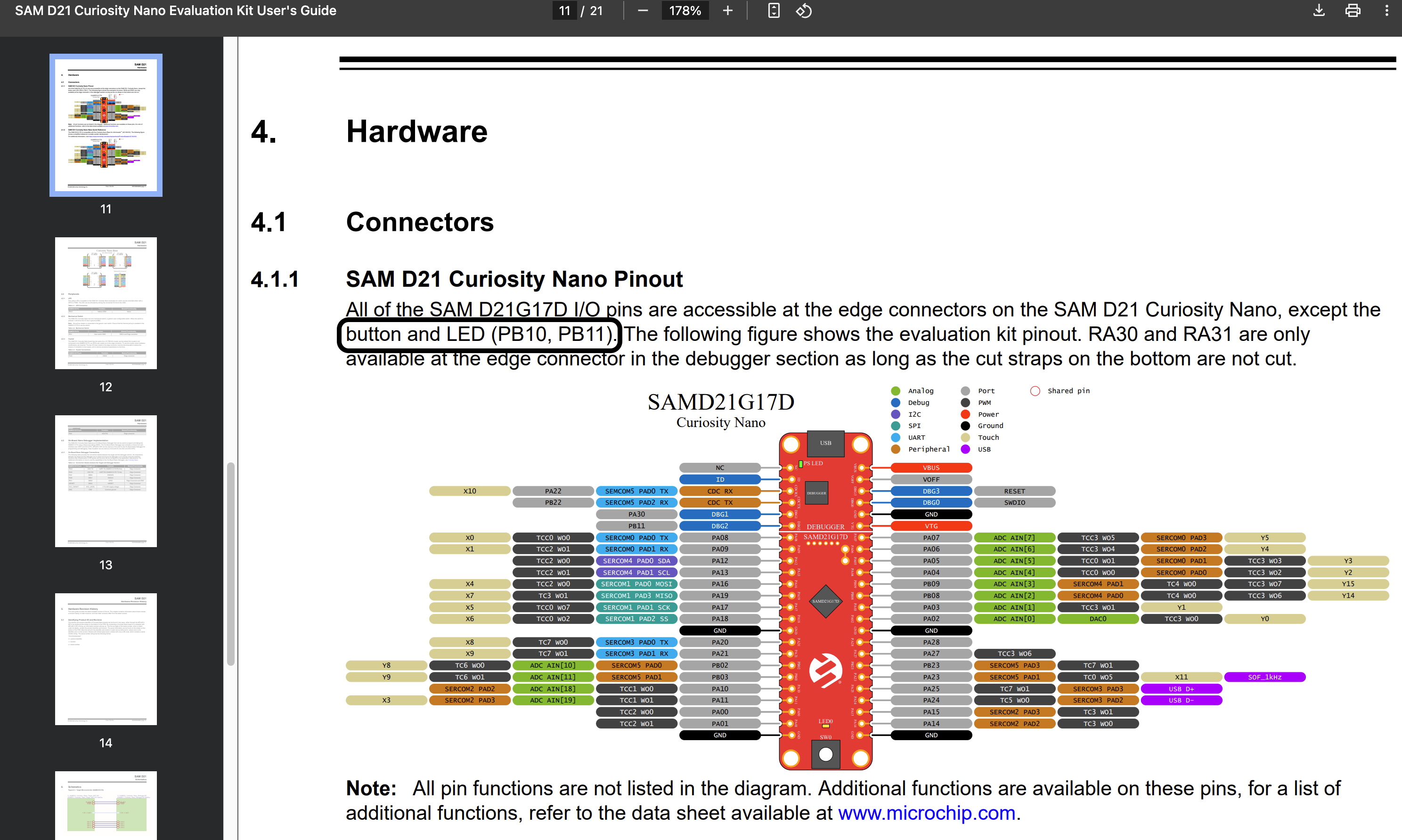
💡 We are going to setup the LED0 and SW0 which are connected to the PB10 and PB11 on the SAMD21 Curiosity board. Always refer to the development board's user manual for the correct pinout and device features list.
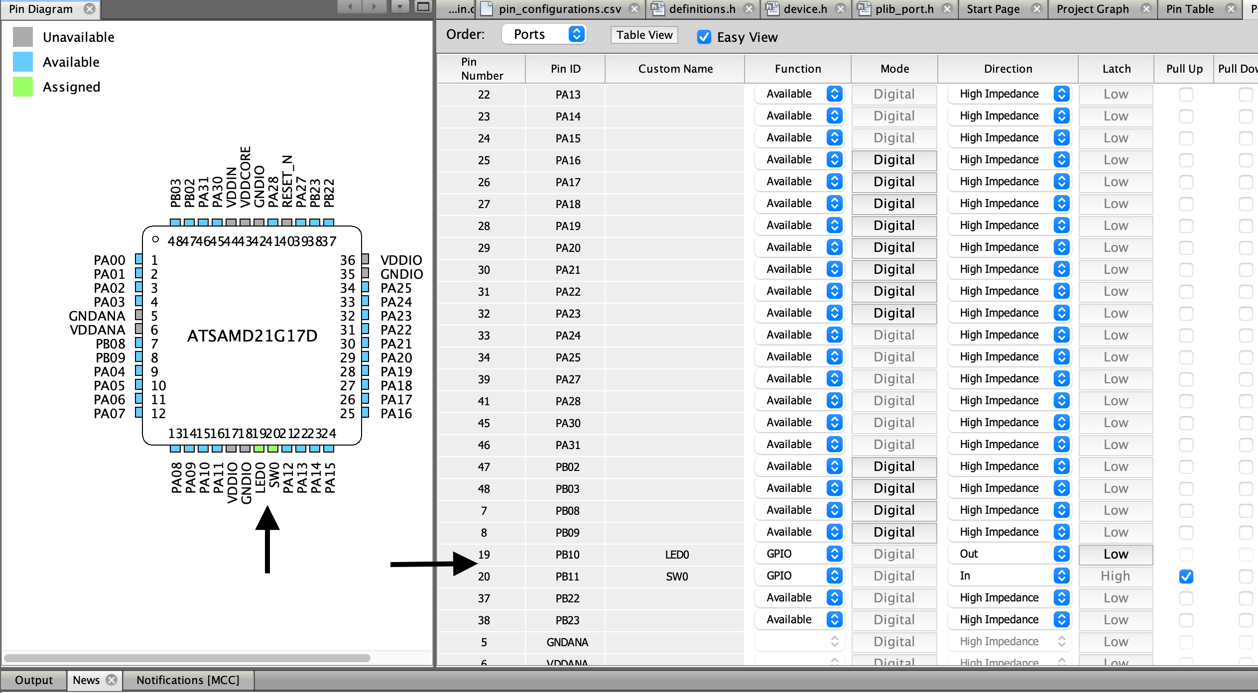
Open the Pin Configuration from the Plugins section and select the "Pin Diagram" tab, open the Pin Settings in a split window for easier workflow.
Select Order to sort by Ports and locate PB10 and PB11 Pin ID. Give the PB10 name of LED0 and PB11 SW0 just like they are named on the PCB and the user manual. Set both pin Functions to GPIO, PB10 is set to Direction Out and the PB11 to Direction In, enable the GPIO pull-up. This will allow us to output a signal to the LED and read a signal from the switch.
Click generate, this will generate starter code for our application, the code will include basic setup for the device settings and clock required to run the application. Our selected pins PB10 and PB11 will also be setup and initialized as per our defined settings.
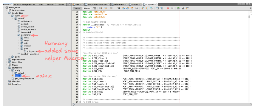
As you can see Harmony has generated the project for us which includes main.c and some additional files inside config folders. The plib_port.h contains generated macros to make working with our selected GPIO very simple. The macros use our own user given names and will allow to autocomplete with ctrl+space or cmd+space on mac.
Working with GPIO 🔌
If we refer to the user manual for the device we can see on pg 16 that the user LED is connected to VCC_TARGET and then to the GPIO PB10 this means it is active LOW and the SW0 is connected to GND when pressed. We can now implement our blinky code.
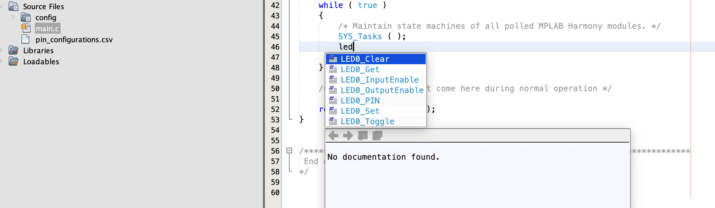
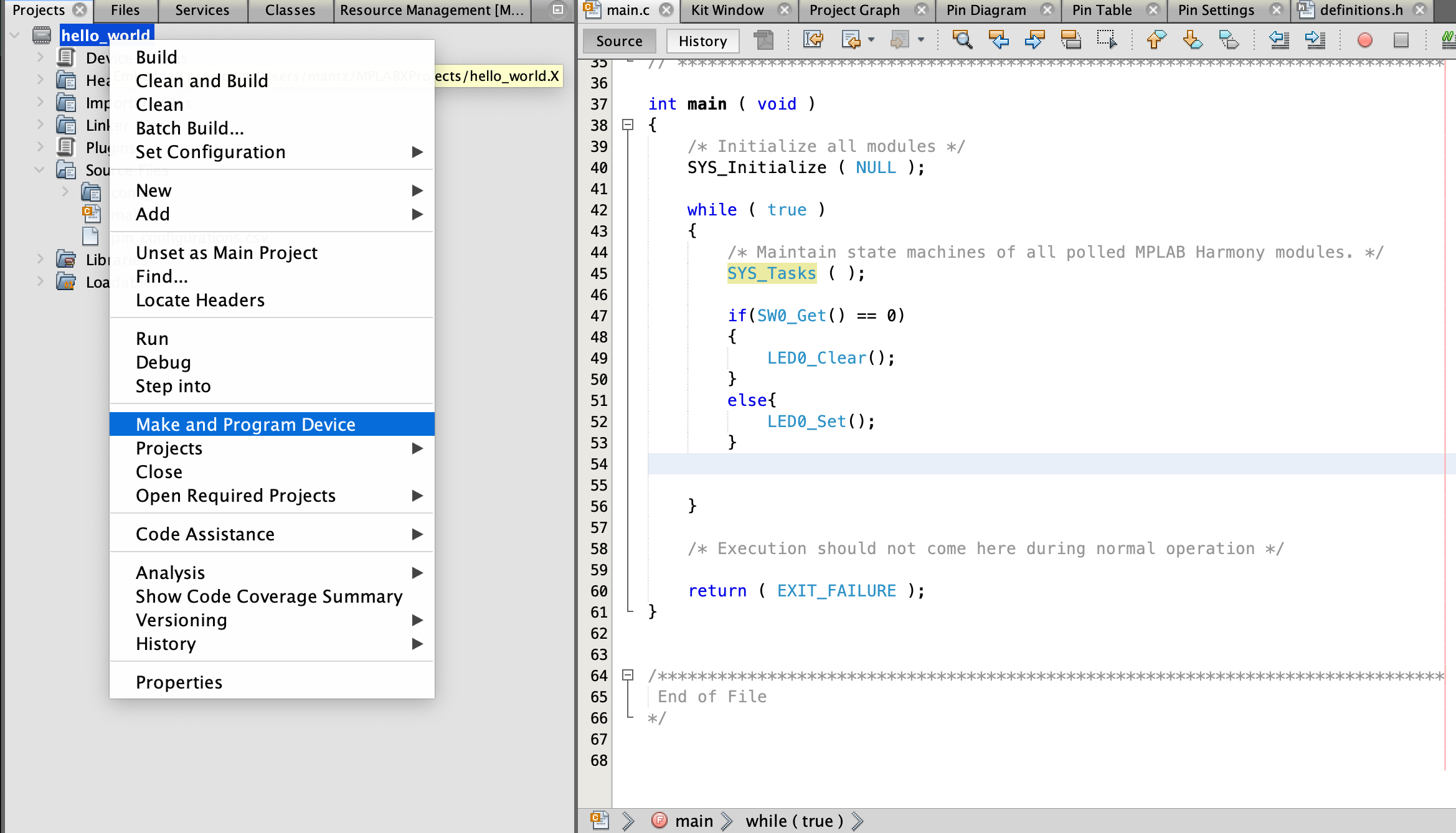
Copy and pase the following on line 47 in main.c
if(SW0_Get() == 0)
{
    LED0_Clear();
}
else{
    LED0_Set();
}
Now right click on the project and select Make and Program Device After programming the device press the button on the development board
When the button SW0 is pressed the LED0 should be ON and turn OFF when released In the above example we used the HArmony generated GPIO macros but all harmony libraries come with a dedicated set of API's which allow user code to interface with the peripherals
Using Harmony Libraries 📚
One of the unique points about Harmony v3 is that all of its components are on GitHub. This makes it easier to keep track of package revisions. Bugs tend to be fixed much quicker as each package can be released individually. I also find it useful to review any open issues for packages I intend to use to make sure there are no issues with features I plan on using.
In our example we will make use of the Harmony V3 Chip Support Package (CSP) The chip support package is the main module that you will use in every project, it contains all the librabies for device peripherals such as timers, ADC, UART and so on. Each package will have it's own github page and each readme will contain a link to the package documentation.
If we look at the Chip Support Package (CSP) documentation, section 2.86 I/O Pin Controller (PORT) we can find all available functions to manipulate and work with the device PORTS which allows indiviual or group configuration of the GPIO pins.
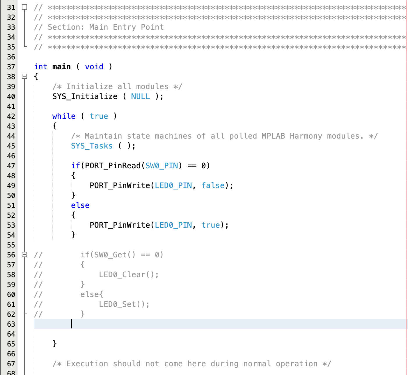
We can replace our code in the previous example using the PORT_PinWrite and PORT_PinRead functions.

Lucky for us the macros LED0_PIN and SW0_PIN have already been generated in port_plib.h and we can use them with the PORT api
#define LED0_PIN PORT_PIN_PB10 #define SW0_PIN PORT_PIN_PB11
if(PORT_PinRead(SW0_PIN) == 0)
{
    PORT_PinWrite(LED0_PIN, false);
}
else
{
    PORT_PinWrite(LED0_PIN, true);
}
Run make and program and we should see the same functionality as in the previous example. The PORT api is a much more powerful way to control the GPIO's and is useful for advanced low level control.