UART Communication Tutorial SAMD21 Harmony
Table of Contents
UART Communication with SAMD21 Harmony 🔌
In this tutorial, we'll set up UART hardware on the SAMD21 Curiosity nano development board. We'll explore different transfer modes - blocking and interrupt ring buffer mode - to understand their pros and cons and ideal use cases. 🚀
UART (Universal Asynchronous Receiver-Transmitter) is a fundamental communication protocol that serves as an invaluable debugging interface for developers. 🛠️
By the end of this guide, you'll be able to print information and visualize signal data from your device on an interactive dashboard! 📊

Contents 📑
- UART Communication with SAMD21 Harmony 🔌
- Setting Up a Harmony Project 🛠️
- UART Hardware Configuration (blocking-mode)
- UART Hardware Configuration (non-blocking ring buffer mode)
- Real-Time Data Visualization
Setting Up a Harmony Project 🛠️
Great news for developers! Most Curiosity boards now include a built-in debugger, eliminating the need for expensive external programming tools. Some boards even offer virtual port capabilities, allowing PC communication through a single USB cable. This means you won't need additional UART-to-USB conversion hardware like the FTDI Basic from Sparkfun.
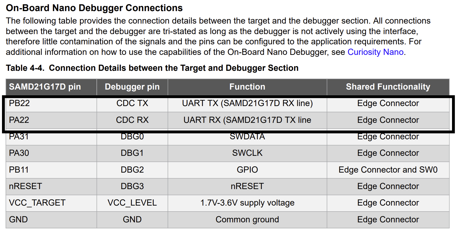
Let's check the user manual - page 13 shows us the crucial connections between the SAMD21 and the debugger.
UART Hardware Configuration (blocking-mode)
We'll need to configure pins PB22 and PA22 in the Harmony configurator. First, follow the Hello World guide to create a new project, then launch the Harmony Configurator (MCC).
The SAMD21 features several general-purpose peripheral modules called SERCOM that can function as UART/I2C/SPI peripherals. According to the manual, our UART pins (PA22 and PB22) can be configured as SERCOM5.
In the device pin Diagram window, select SERCOM5 PAD_0 and PAD_2, then find the SERCOM module in device resources -> Peripherals.
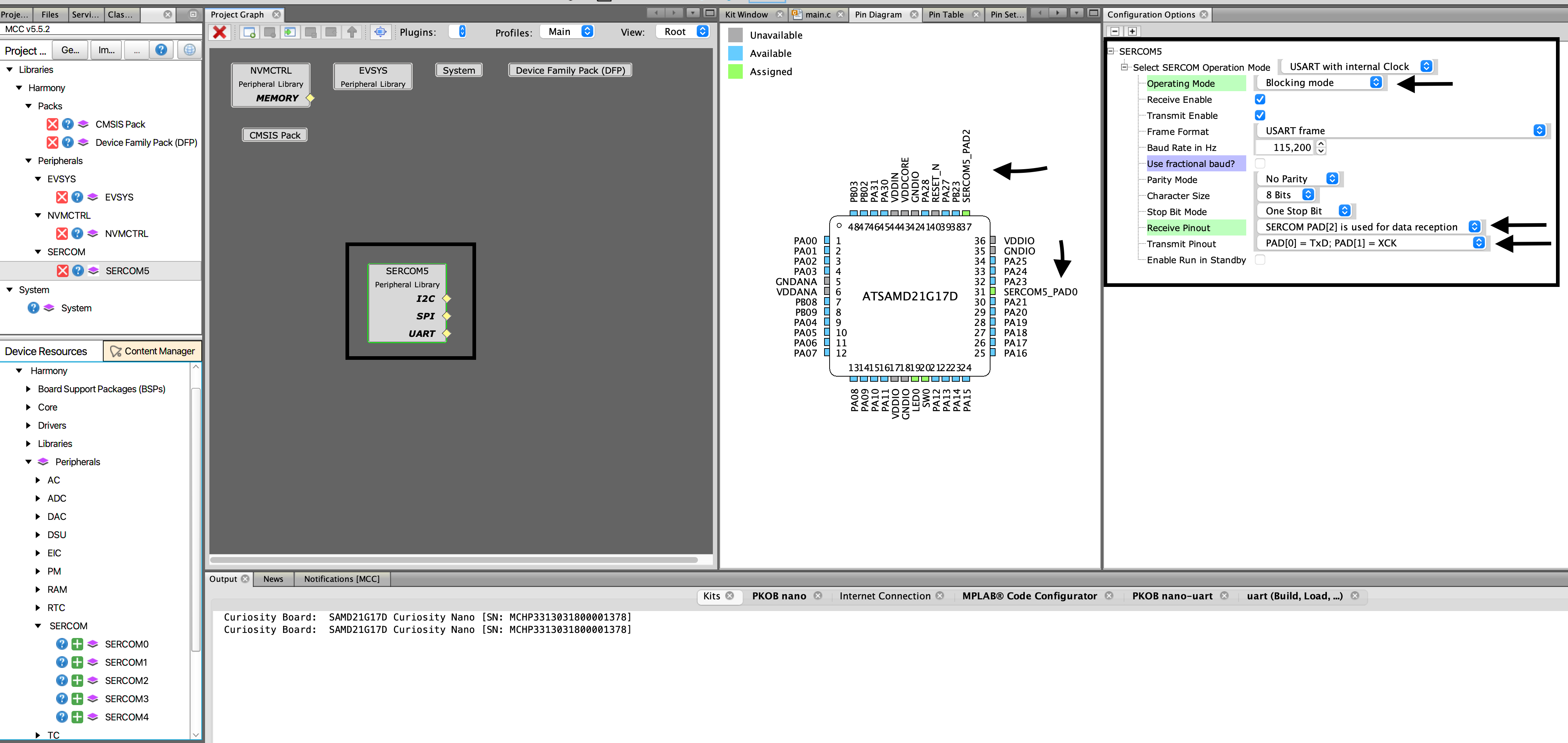
For our initial implementation, we'll use Blocking mode. 📝 Since the CDC TX connects to PB22, this will be our receive pin in the configuration. Set receive pinout to PAD[2] and transmit to PA22 PAD[0].
Click generate, and voilà - UART setup complete! ✨
In the main.c add the following code.
        if (PORT_PinRead(SW0_PIN) == 0) {
            PORT_PinWrite(LED0_PIN, false);
        } else {
            PORT_PinWrite(LED0_PIN, true);
        }

        char myData[] = {"Hello from microbytes! \n"};
        // This API blocks until the requested bytes are transmitted out
        SERCOM5_USART_Write(&myData, sizeof(myData));


        volatile static int cycles = 1000000;
        while (cycles--)
        {
        __NOP(); // or NOP(); depending on your compiler
        }
        cycles = 1000000;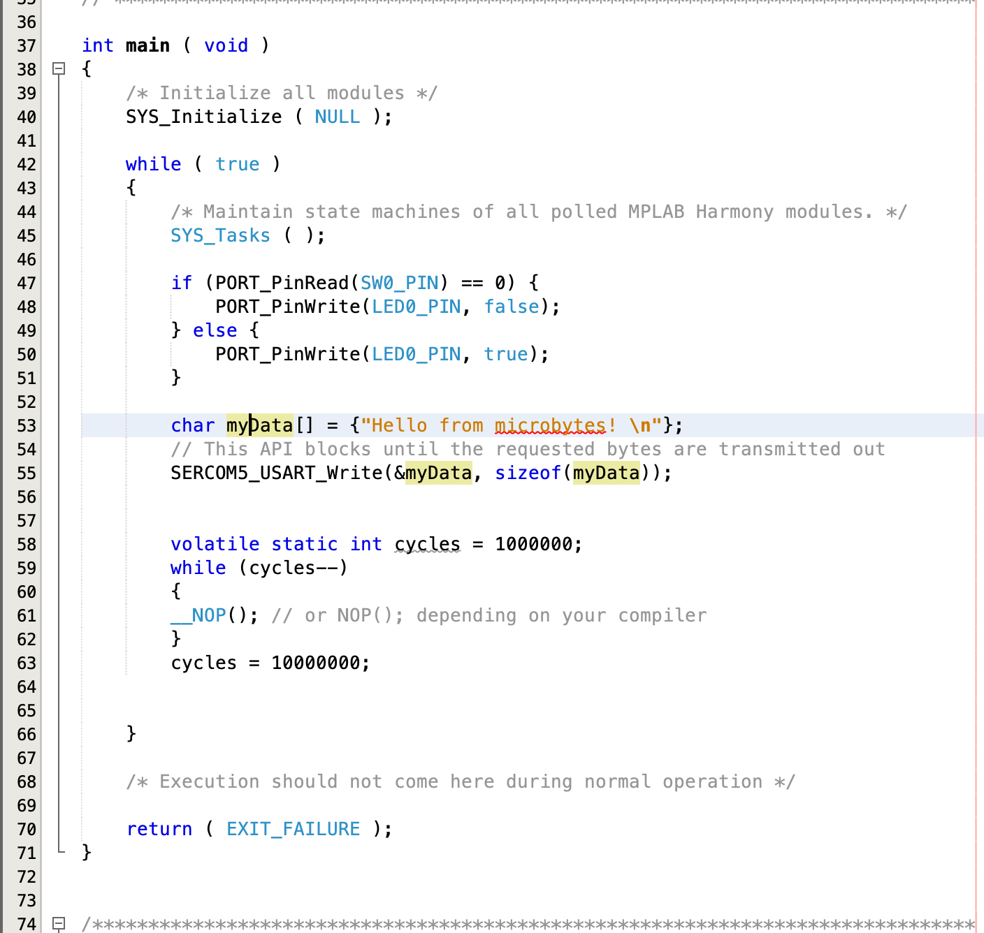
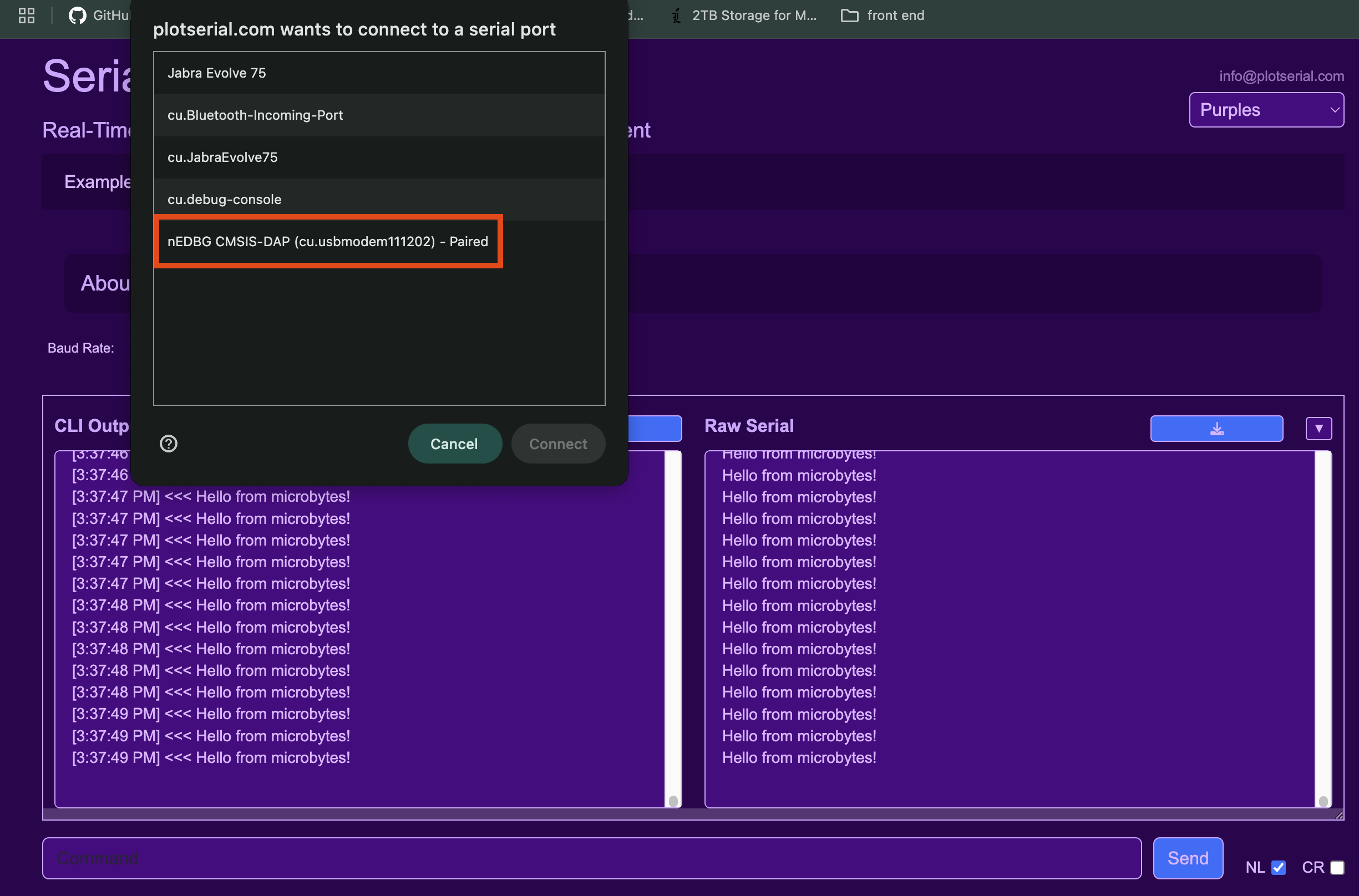
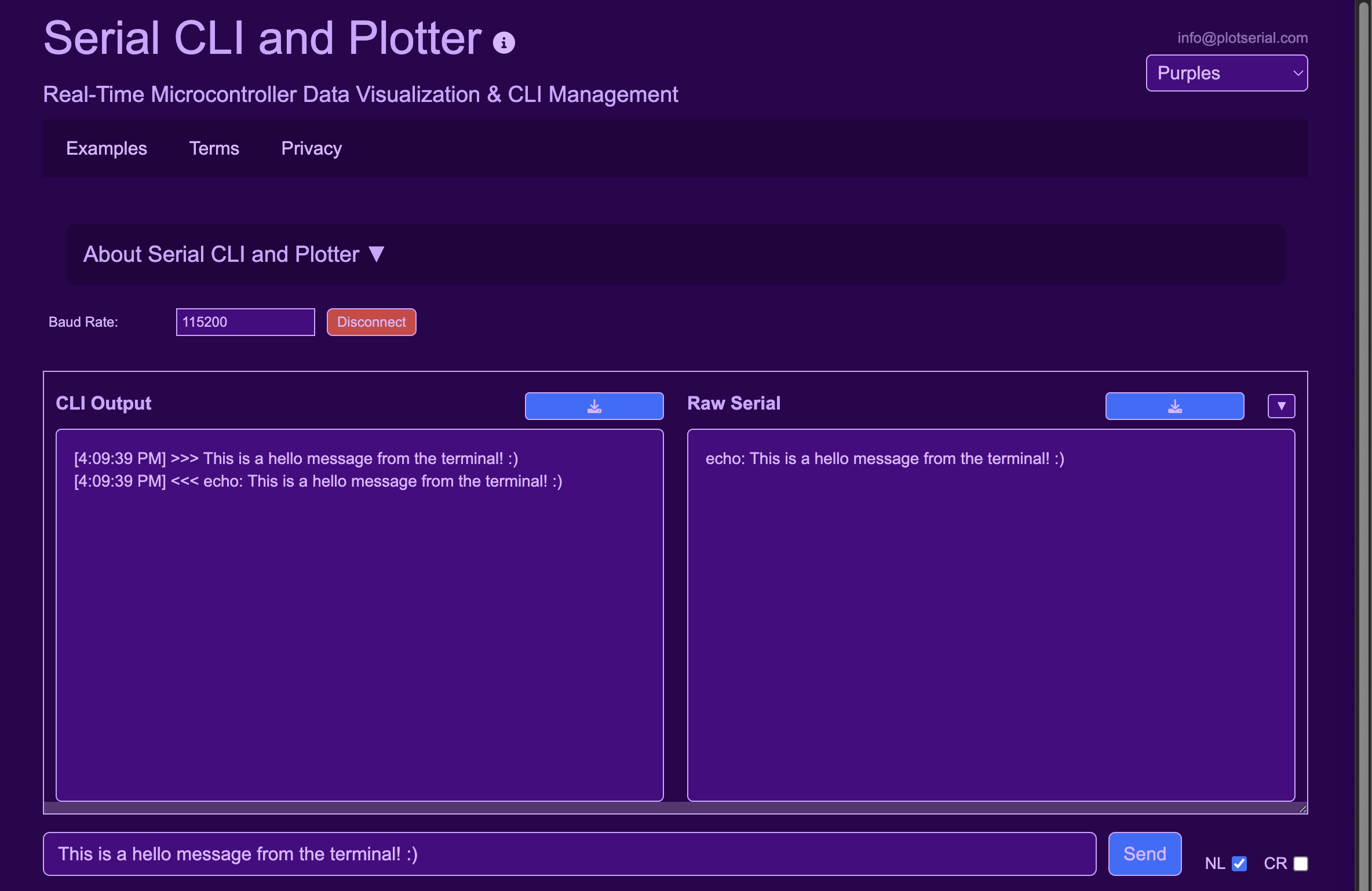
In this example, we included a basic delay using __NOP(); to reduce data transmission frequency. You can test your application by connecting to the debugger comport using plotSerial tool - just click connect and select your device! 🔍
If we look at the Chip Support Package (CSP) documentation, section 2.110 Serial Communication Interface (SERCOM) we can find all available SERCOM UART API's we used the SERCOM5_USART_Write to write to the UART.
We can also receive data in blocking mode using *bool SERCOMx_USART_Read( void buffer, const size_t size )
The function will pause code execution until the number of requested bytes is receieved.
UART Hardware Configuration (non-blocking ring buffer mode)
Most applications can't afford to operate in blocking mode and benefit from interrupt-based non-blocking operating modes. Harmony framework abstracts some of this complication and allows the driver to seamlessly operate in non-blocking mode.
Navigate to the MCC SERCOM module configuration and change the operating mode to ring buffer.
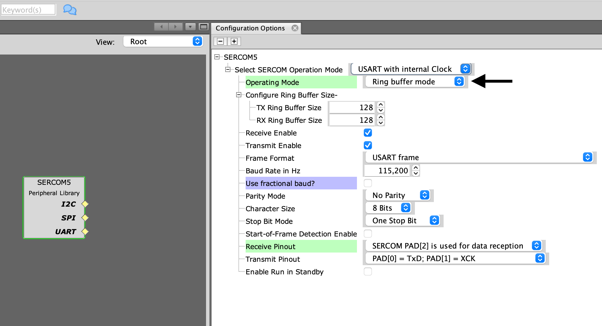
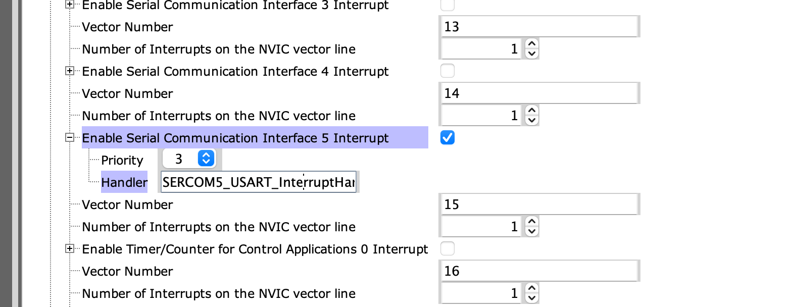
One of the great and also not-so-great features of using something like the Harmony framework is that it abstracts a lot of the complexity but this can also result in technical debt especially when setting up complex peripherals and then trying to debug an issue. In this case, we have selected ring buffer mode of the SERCOM UART and without telling us Harmony has made some modifications to the NVIC and enabled interrupts for the UART as well as generating a callback handler.
We will now write a simple echo application which will wait for a new-line char and then echo our message back. We will make use of the non-blocking API's to check for available bytes and read until the '\n' char then use write API to send the data back as echo.
The driver now operates in non-blocking mode, we no longer need to request and wait for the bytes to arrive, the bytes will automatically be placed in a queue (ring buffer) once received. We can query this queue using the API (see the CSP documentation 2.110)
size_t SERCOMx_USART_ReadCountGet( void )
We can check the value each loop and only process the data when it is available. For those familiar with Arduino this is similar to Serial.available() function.
The code below fetches the number of available bytes and then checks if the received byte or char is \n. If new line is not received it checks if there are more bytes available and keep looping until all bytes have been processed. As soon as a new-line char is received the echo: response is assembled and written back to UART. The full example is included below.
/*******************************************************************************
  Main Source File

  Company:
    Microchip Technology Inc.

  File Name:
    main.c

  Summary:
    This file contains the "main" function for a project.

  Description:
    This file contains the "main" function for a project.  The
    "main" function calls the "SYS_Initialize" function to initialize the state
    machines of all modules in the system
 *******************************************************************************/

// *****************************************************************************
// *****************************************************************************
// Section: Included Files
// *****************************************************************************
// *****************************************************************************

#include <stddef.h>                     // Defines NULL
#include <stdbool.h>                    // Defines true
#include <stdlib.h>                     // Defines EXIT_FAILURE
#include "definitions.h"                // SYS function prototypes
#include "string.h"
#include "stdio.h"


// *****************************************************************************
// *****************************************************************************
// Section: Main Entry Point
// *****************************************************************************
// *****************************************************************************
#define RX_BUFFER_SIZE 128
int main ( void )
{
    /* Initialize all modules */
    SYS_Initialize ( NULL );
    static char rxBuffer[RX_BUFFER_SIZE];
    static size_t rxIndex = 0;
    size_t availableBytes;
    char receivedChar;

    while ( true )
    {
        /* Maintain state machines of all polled MPLAB Harmony modules. */
        SYS_Tasks ( );

        if (PORT_PinRead(SW0_PIN) == 0) {
            PORT_PinWrite(LED0_PIN, false);
        } else {
            PORT_PinWrite(LED0_PIN, true);
        }

//        char myData[] = {"Hello from microbytes! \n"};
//        // This API blocks until the requested bytes are transmitted out
//        SERCOM5_USART_Write(&myData, sizeof(myData));

    availableBytes = SERCOM5_USART_ReadCountGet();

    while (availableBytes > 0)
    {
        // Read a single byte
        if (SERCOM5_USART_Read((uint8_t*)&receivedChar, 1) == true)
        {
            if (rxIndex < RX_BUFFER_SIZE - 1)
            {
                rxBuffer[rxIndex++] = receivedChar;
            }

            if (receivedChar == '\n')
            {
                rxBuffer[rxIndex] = '\0'; // Null-terminate the string

                // Build echo response
                char echoBuffer[RX_BUFFER_SIZE + 10];
                snprintf(echoBuffer, sizeof(echoBuffer), "echo: %s", rxBuffer);

                // Send response back
                SERCOM5_USART_Write((uint8_t*)echoBuffer, strlen(echoBuffer));

                // Reset buffer index for next message
                rxIndex = 0;
            }
        }

        // Update available bytes again in case more data has arrived
        availableBytes = SERCOM5_USART_ReadCountGet();
    }


        volatile static int cycles = 1000000;
        while (cycles--)
        {
        __NOP(); // or NOP(); depending on your compiler
        }
        cycles = 1000000;


    }

    /* Execution should not come here during normal operation */

    return ( EXIT_FAILURE );
}


/*******************************************************************************
 End of File
*/
Real-Time Data Visualization
we can now utilize the implemented UART driver to give us some useful information about our application, let's say we want to monitor sensor signals or motor angle. We can implement the sample from plotSerial.com
update includes section
#include <stddef.h>                     // Defines NULL
#include <stdbool.h>                    // Defines true
#include <stdlib.h>                     // Defines EXIT_FAILURE
#include "definitions.h"                // SYS function prototypes
#include "string.h"
#include "stdio.h"
#include <math.h>
#include <stdarg.h>
Then add the following function somewhere above main, this allows us to convert key value pairs into a JSON formatted string which can be used by the plotSerial application. Using Json is not the most efficient way to transport data, but it makes it easy for compatability with many other languages such as python and java script.
void format_json(char *buffer, size_t buffer_size, int num_pairs, ...) {
    va_list args;
    va_start(args, num_pairs);

    size_t offset = snprintf(buffer, buffer_size, "{");

    for (int i = 0; i < num_pairs; i++) {
        const char *key = va_arg(args, const char *);
        double value = va_arg(args, double);

        offset += snprintf(buffer + offset, buffer_size - offset,
                        "\"%s\": %.2f%s", key, value,
                        (i < num_pairs - 1) ? ", " : "");
    }

    snprintf(buffer + offset, buffer_size - offset, "}\n");
    va_end(args);
}
and add the following code in the main to generate some random data.
// Simulate dynamic data changing over time
sine_value = sin(i * 0.1);
format_json(buffer, sizeof(buffer), num_pairs,
"temp", sine_value,
"hum", (sine_value * 2));
i++;
if(i == 32)
{
i = 0;
}
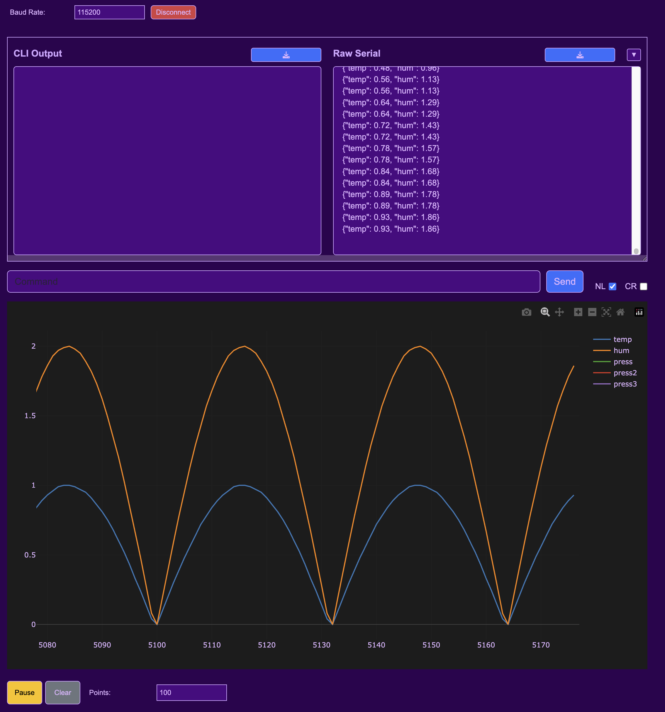
SERCOM5_USART_Write((uint8_t*)buffer, strlen(buffer));The result is a real time plot we can use to monitor what our device is doing.
Here is the full Code example
/*******************************************************************************
  Main Source File

  Company:
    Microchip Technology Inc.

  File Name:
    main.c

  Summary:
    This file contains the "main" function for a project.

  Description:
    This file contains the "main" function for a project.  The
    "main" function calls the "SYS_Initialize" function to initialize the state
    machines of all modules in the system
 *******************************************************************************/

// *****************************************************************************
// *****************************************************************************
// Section: Included Files
// *****************************************************************************
// *****************************************************************************

#include <stddef.h>                     // Defines NULL
#include <stdbool.h>                    // Defines true
#include <stdlib.h>                     // Defines EXIT_FAILURE
#include "definitions.h"                // SYS function prototypes
#include "string.h"
#include "stdio.h"
#include <math.h>
#include <stdarg.h>

void format_json(char *buffer, size_t buffer_size, int num_pairs, ...) {
    va_list args;
    va_start(args, num_pairs);

    size_t offset = snprintf(buffer, buffer_size, "{");

    for (int i = 0; i < num_pairs; i++) {
        const char *key = va_arg(args, const char *);
        double value = va_arg(args, double);

        offset += snprintf(buffer + offset, buffer_size - offset,
                        "\"%s\": %.2f%s", key, value,
                        (i < num_pairs - 1) ? ", " : "");
    }

    snprintf(buffer + offset, buffer_size - offset, "}\n");
    va_end(args);
}

// *****************************************************************************
// *****************************************************************************
// Section: Main Entry Point
// *****************************************************************************
// *****************************************************************************
#define RX_BUFFER_SIZE 128
int main ( void )
{
    /* Initialize all modules */
    SYS_Initialize ( NULL );
    static char rxBuffer[RX_BUFFER_SIZE];
    static size_t rxIndex = 0;
    size_t availableBytes;
    char receivedChar;
    char buffer[256];
    int num_pairs = 2;
    double sine_value = 0.0;
    int i =0;

    while ( true )
    {
        /* Maintain state machines of all polled MPLAB Harmony modules. */
        SYS_Tasks ( );

        if (PORT_PinRead(SW0_PIN) == 0) {
            PORT_PinWrite(LED0_PIN, false);
        } else {
            PORT_PinWrite(LED0_PIN, true);
        }

//        char myData[] = {"Hello from microbytes! \n"};
//        // This API blocks until the requested bytes are transmitted out
//        SERCOM5_USART_Write(&myData, sizeof(myData));

    availableBytes = SERCOM5_USART_ReadCountGet();

    while (availableBytes > 0)
    {
        // Read a single byte
        if (SERCOM5_USART_Read((uint8_t*)&receivedChar, 1) == true)
        {
            if (rxIndex < RX_BUFFER_SIZE - 1)
            {
                rxBuffer[rxIndex++] = receivedChar;
            }

            if (receivedChar == '\n')
            {
                rxBuffer[rxIndex] = '\0'; // Null-terminate the string

                // Build echo response
                char echoBuffer[RX_BUFFER_SIZE + 10];
                snprintf(echoBuffer, sizeof(echoBuffer), "echo: %s", rxBuffer);

                // Send response back
                SERCOM5_USART_Write((uint8_t*)echoBuffer, strlen(echoBuffer));

                // Reset buffer index for next message
                rxIndex = 0;
            }
        }

        // Update available bytes again in case more data has arrived
        availableBytes = SERCOM5_USART_ReadCountGet();
    }


    // Simulate dynamic data changing over time

        sine_value = sin(i * 0.1);

        format_json(buffer, sizeof(buffer), num_pairs,
                    "temp", sine_value,
                    "hum", (sine_value * 2));
        i++;
        if(i == 32)
        {
            i = 0;
        }
        SERCOM5_USART_Write((uint8_t*)buffer, strlen(buffer));


        volatile static int cycles = 1000000;
        while (cycles--)
        {
        __NOP(); // or NOP(); depending on your compiler
        }
        cycles = 1000000;


    }

    /* Execution should not come here during normal operation */

    return ( EXIT_FAILURE );
}


/*******************************************************************************
 End of File
*/
Using UART in ring buffer mode is incredibly powerful and efficient for non-blocking applications like CLI (Command Line Interface) 🖥️. When commands are typed by humans (relatively slow input), the ring buffer accumulates data and processes it in the background inside the interrupt.
The buffer is also perfect for automation scenarios where commands arrive at irregular intervals. By adjusting the buffer size, you can store multiple commands or data samples and process them as they arrive - no data loss! 💾
The Harmony drivers have implemented these modes and features for us, letting us focus on application logic rather than reinventing common design patterns. We'll explore the higher-level USART driver in our next post! 🚀
You might have noticed we accessed UART via the SERCOM_USART API - this is SAMD21-specific, as SERCOM hardware isn't present on PIC32 microcontrollers. In our next post, we'll see how Harmony provides higher-level peripheral access and interfaces with various services to expand capabilities and cross-hardware compatibility. The goal of Harmony V3 is to enable portable application development across all 32-bit devices while maintaining low-level hardware control when needed. 🎯